07-27-2005, 02:40 PM
|
#1
|
|
Gone
Join Date: Mar 2004
Location: Lockport Ny
Posts: 19,244
|
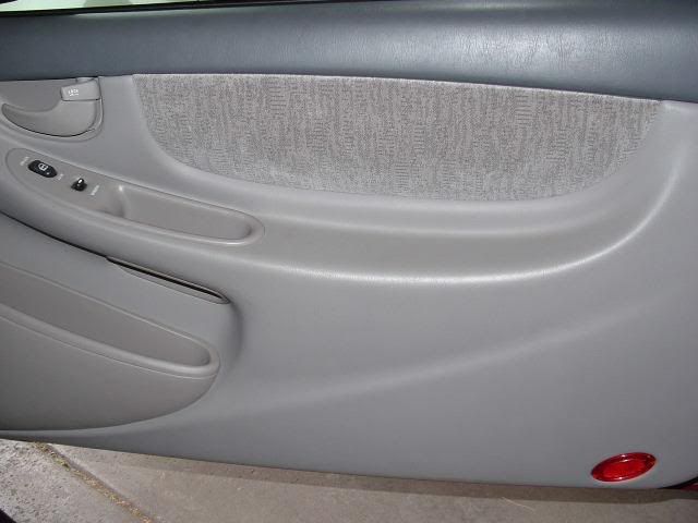
This is the How-To for putting LED’s in the map cubby on the Alero door.
Level of Difficulty: Moderate.
The tools required are: a hobby tool kit. (screwdriver bits, torque bits, and sockets),3/32” + 13/64” drill bits, a soldering gun, wire strippers, a long screwdriver (any type), a dremel;file;or sand paper, and a pair of pliers.
Materials Required: 3 LED’s of your color choice, Duct tape, Super glue, several lengths of wire (I’m using 18ga speaker wire)
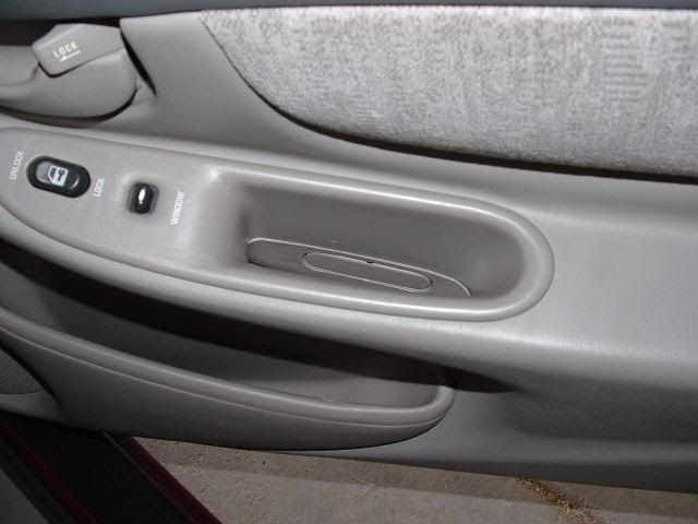
Step 1: Open your car door, in a location that it will not get hit or damaged in! Pop off the cover under the inside handle. (just below the handle to open the door) and reveal 2 large screws. The other cover is the red reflector in the bottom corner. Just put a screwdriver under the edge and pry it up.
|

|

|
|
07-27-2005, 02:42 PM
|
#2
|
|
Gone
Join Date: Mar 2004
Location: Lockport Ny
Posts: 19,244
|
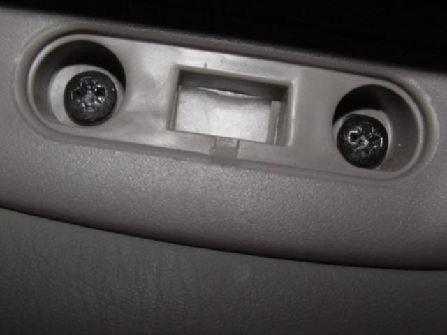
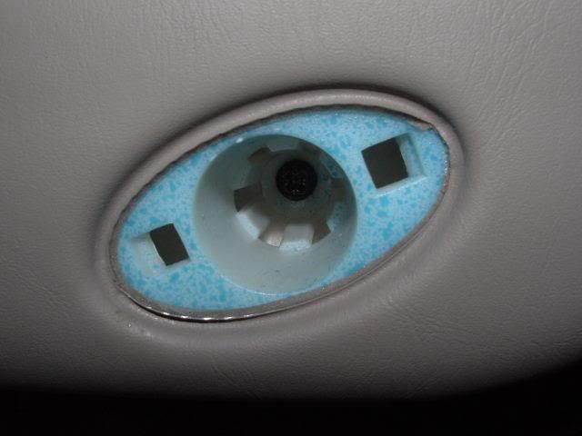
Pics of screw covers off.
  |
|
|
|
|
07-27-2005, 02:43 PM
|
#3
|
|
Gone
Join Date: Mar 2004
Location: Lockport Ny
Posts: 19,244
|
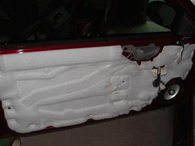
Step 2: Remove the screws (3 of them) and place then in a safe location. You don’t want these things roll’n away on ya!
Step 3: Pry the inside of the door off. I found it easier to pop the tweeter off the door and grab where the bottom of the tweeter casing sits. Start on one side and work your way around. Pry gently but firmly. If you just go crazy pulling it off, you’ll break all the little green plugs that hold it in place.
Step 4: Once your door is unsnapped, lift up on the entire piece and lift it up off the window edging. I took my window edge right out and put it in the back seat. Just to be sure it didn’t fall off or get misplaced.
|
|
|
|
|
07-27-2005, 02:45 PM
|
#4
|
|
Gone
Join Date: Mar 2004
Location: Lockport Ny
Posts: 19,244
|
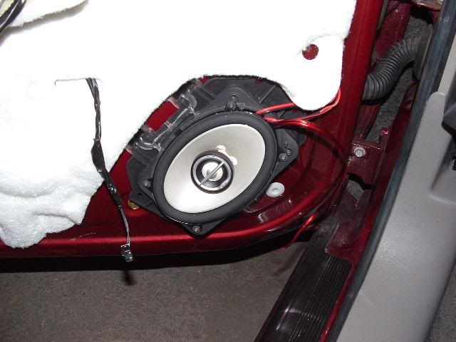
Step 5: Congratulations, your door is off. If you want to change your 4x6’s now is a good time since they are coming out soon too.
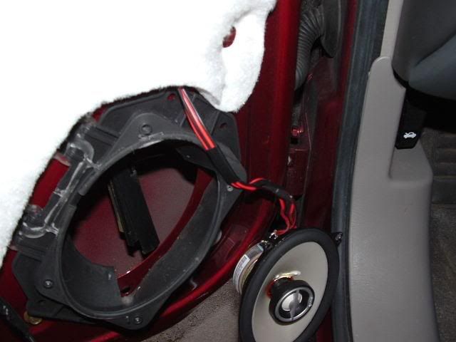
Step 6: Take the hobby kit (or torque bits) that you have and unscrew the 4x6 speaker. Just take it out and place it next to the hole where it was. (you can just stick it to the door, the magnet will hold it there) The opening for the speaker will be used later.
|
|
|
|
|
07-27-2005, 02:47 PM
|
#5
|
|
Gone
Join Date: Mar 2004
Location: Lockport Ny
Posts: 19,244
|
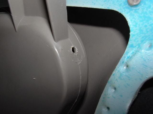
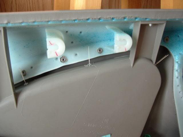
Step 7: Take the inside of the door over to where you can work on it easier. Measure off where you want the LED’s. I put one right on the bend and one just inside each of the plastic braces. I took a small screw and pushed the tip into the plastic to mark the spot where I wanted the hole.
Step 8: After really agrivating myself on the first attempt at drilling one of these holes, I figured it out. Take the pliers and hold the smaller drill bit in place. Then with the other hand, hold the soldering gun tip near the base of the drill bit. Hold it there for a minute or two and the bit should heat up enough to push through the plastic like its butter.
|
|
|
|
|
07-27-2005, 02:49 PM
|
#6
|
|
Gone
Join Date: Mar 2004
Location: Lockport Ny
Posts: 19,244
|
Step 9a: Take the larger bit (13/64”) and use the pliers to screw it down into the hole in the bend. It shouldn’t take much to get it through the plastic. Twist it down about three quarters of the way down the bit, then w/ the pliers pull it straight out. This will pull out any unnecessary left over plastic as well as leave a nice clean hole for the LED to fit in.
[pic above]
Step 9b: Take the same drill bit and now take it very securely to the screwdriver. (shown in picture below) Flip the door around and put the drill bit tip down into the hole you melted before. Repeat procedure from last time. Twist the bit down into the hole, then pull it out. Then just do the same for the other hole and your done w/ the first major part of the project!
|
|
|
|
|
07-27-2005, 02:52 PM
|
#7
|
|
Gone
Join Date: Mar 2004
Location: Lockport Ny
Posts: 19,244
|
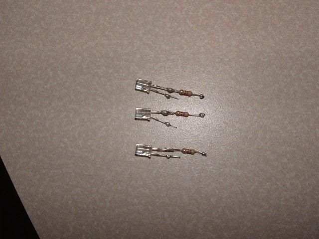
Step 10: This is the middle (easy) part of the project. Take your sanding device (paper, dremel or file) and file the tips of the LED’s off. Not the entire tip! Just about 1/16th of an inch. This will spread out the light much more then just the narrow beam that it was before. (you should be able to set the LED’s tip down on a flat surface and be able to stand them up)
Step 11: Press the LED’s into their holes. Make sure everything looks alright. The holes should be just big enough to fit the LED but not the back edge of it. Now solder each of the resistors onto one of the leads on the LED. It doesn’t matter which side, just pick one. Feel free to trim the leads down (but leave the longer one LONGER and the shorter one SHORTER. Its for reference, don’t cut them the same length) on each so you don’t have a ton of unprotected metal hanging around in there. (if they ever touch the LED will blow) You can duct tape them, cover the leads w/ hot glue (very handy), Silicon gel, or my new personal favorite “liquid electrical tape” that stuff is worth its weight in gold!
|
|
|
|
|
07-27-2005, 02:55 PM
|
#8
|
|
Gone
Join Date: Mar 2004
Location: Lockport Ny
Posts: 19,244
|
Step 12: Now solder a wire to each lead. Each LED has a flat side on the clear plastic (or a long lead and a short lead) Make sure to use separate colored wires for each lead. Keep this uniform for each LED you use, as well. It makes life A LOT easier. (the over beading of solder is for illustration purposes only. don't use that much)
|
|
|
|
|
07-27-2005, 02:57 PM
|
#9
|
|
Gone
Join Date: Mar 2004
Location: Lockport Ny
Posts: 19,244
|
Step 13: Take each of the same colored wires, strip the ends off and twist them all together. This will make one bigger connection, but you’ll end up w/ one power and one ground. I used some duct tape here as well, just to hold the wires together inside the door.
Step 14: If everything looks ok, now but a small bead of super glue on the edge of each LED. You don’t need much… but make sure after it dried that they are firmly in there. After the glue is set, you are almost done. Just gotta do a little wire fishing and wiring and we’re done.
|
|
|
|
|
07-27-2005, 03:03 PM
|
#10
|
|
Gone
Join Date: Mar 2004
Location: Lockport Ny
Posts: 19,244
|
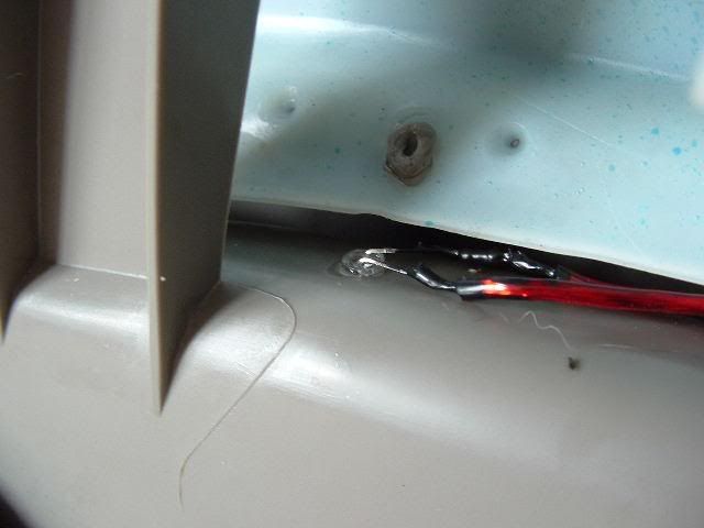
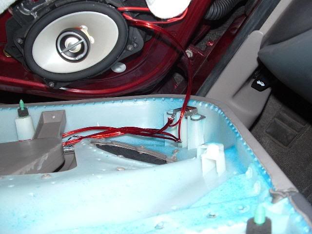
Step 15: This can be started while the glue is setting on the LED’s. Take a spool of wire and take a mock measuring of how much you’ll need. All of my interior wiring is brought into my center console, so I measured out how much from the door to there, then added about a foot, for good measure.
Step 16: This was the hardest part I encountered. Getting power from the center console to the door. The rubber “S” shaped tube is where I fished my wire through. I found it MUCH easier to put it through from the door side, and grab it from the interior side. I was able to get my hand into the hole where the 4x6 is, and get the wire more then half way through the S. Pushing the rubber up so its nearly a straight line also helps. After about an eternity of frustration I finally got it and started feeding it through, leaving plenty to wire to outside the door. Leave the wire outside the rubber harness for the speaker, and put the speaker back on.
-----
Since I did this part alone, I don't have any pics for you as a reference. Just be warned, if you do feed the wire through the 4x6 hole like I did, you will cut up your hand. There is alot of sharp metal in there. If there is an easier way, feel free to post up. I got like 10 small metal papercuts by time I was done.
-----
Step 17: Wire the power and ground to wherever you desire inside the car. Depending on when you want these lights turning on, depends on what you wire it to. I have a wire block that everything connected to it, turns on with the headlights, at night. I simply unscrew a opening and insert the wires.
|
|
|
|
|
07-27-2005, 03:04 PM
|
#11
|
|
Gone
Join Date: Mar 2004
Location: Lockport Ny
Posts: 19,244
|
Step 18: Now that your glue is dry, we can get the wires soldered. Take the door back out to the car. Now turn your headlights on (if wiring the same way I did) and touch your indoor wire leads to the on door wire leads. Make sure the LED’s light up. If not, try reversing the indoor leads on the others. (positive to positive, neg to neg. if backwards nothing works) Also, with the lights on, make sure that the indoor power and ground DO NOT touch. This will blow fuses in your car. Its never fun to find them. Be careful! Make sure you turn your head lights off before proceeding.
Step 19: Assuming that everything lit up nicely, now twist the Power leads together and Ground leads together. Now you have the power and grounds all connected. Make it semi-permanent by soldering them.
|
|
|
|
|
07-27-2005, 03:06 PM
|
#12
|
|
Gone
Join Date: Mar 2004
Location: Lockport Ny
Posts: 19,244
|
Step 20: Very Important. Make sure you cover these connections w/ some kind of protection. They will be just inside the door, and lord knows if any water touches them its gonna short out. I used a good coating of my liquid tape. As mentioned before, hot glue works good, as well as silica gel. If you have electrical tape that’d work great as well.
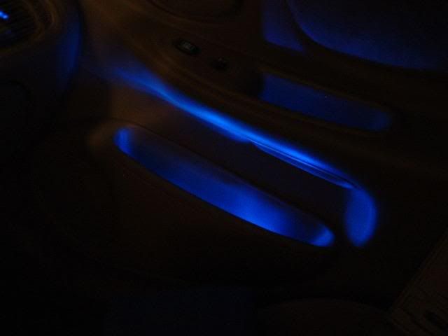
Step 21. Now you just have to simply put your door back on. Reverse the first several steps and your done. Turn on the power and appreciate the glow!
I hope this helps anyone who wants to do the same project. If you have any questions about something feel free to pm me.  |
|
|
|
|
08-01-2005, 10:20 PM
|
#13
|
|
|
lookin sweet. pretty creative.
|
|
|
|
|
08-01-2005, 10:39 PM
|
#14
|
|
GX Member
Join Date: Jul 2005
Location: Eau Claire, WI
Posts: 28
|
Love the glow... You've definitely got me interested!
|
|
|
|
|
04-22-2006, 12:15 PM
|
#15
|
|
GL Member
Join Date: Nov 2004
Location: Hamilton,Ontario
Posts: 331
|
is it possable to just hook them to the speakers? since they have resistors NOTE:fronts are not run off amp
im going to try it. i guess plz someone reply jus yes or no thanx boyz
|
|
|
|
|
04-22-2006, 02:40 PM
|
#16
|
|
GL Member
Join Date: Nov 2004
Location: Hamilton,Ontario
Posts: 331
|
Guess it doesnt work anyone know why? tested the leds on battery before hooking them up.
|
|
|
|
|
04-22-2006, 06:48 PM
|
#17
|
|
Gone
Join Date: Mar 2004
Location: Lockport Ny
Posts: 19,244
|
if you connect them directly to the battery, your going to need that resistor... or else the LED will be REALLY bright for a millisecond, then explode.
also, i don't think connecting to the speaker will work, since it'll be varying voltage when the speaker is on, and none w/ it off.
|
|
|
|
|
04-22-2006, 09:01 PM
|
#18
|
|
GL Member
Join Date: Nov 2004
Location: Hamilton,Ontario
Posts: 331
|
to much voltage going to the speakers from my head unit i guess... im now running everything to the center consol like you have done cherrington17 thanks for the help.. i jus installed a led toggle switch so i can jus keep adding stuff on. should i just grab the power from the line into the fuse box? jus currious how you have your main power run. thanks again cherrington. o yeah i shoulda added another led. i only did 2 in each. stupid me i thought it would be to bright.
|
|
|
|
|
04-22-2006, 10:27 PM
|
#19
|
|
Gone
Join Date: Mar 2004
Location: Lockport Ny
Posts: 19,244
|
it helps if you sand down the tip. two would be decent, just not really bright.
and yes, i ran one line from the fuse box. personally, i got a line from over there (not sure which, i can look tomarrow) that turns on w/ the headlights, when it gets dark enough. so my vents and doors, light up at night (around dusk) and they don't run during the day.
EDIT: the power actually comes from the lights for the shift console. i cut the wires (due to led lights in there too) and ran the power and ground there to separate distros. then ran the wires back to the lights. that gives you a power, and ground distro, that turn on at night...
under my center console i have one big distro for Always On Pwr, one big one for Gnd, and 3 for led's. one for misc On at Night, one for Blue Led's at Night, and one for Red at Night.
its chaotic... but Very functional.
good luck. |
|
|
|
|
05-29-2011, 10:23 PM
|
#20
|
|
GL Member
Join Date: Apr 2011
Location: Soldotna, Alaska
Posts: 348
|
what size resistors are you using?
__________________
'00 Alero GL - 11X,XXX miles
-4500K/6000k/30000k(purple) HID's Hi/Lo/Fogs
-Carbon fiber pillars, door handles, and Gas cover
-Optima yellow top. This battery went end over end in my jeep (not strapped down) 13 times for 75 feet. and now is in my alero. one tough battery
-Cleared Corners/Painted Bezels
|
|
|
|
|
Currently Active Users Viewing This Thread: 1 (0 members and 1 guests)
|
|
|
| Thread Tools |
Search this Thread |
|
|
|
| Display Modes |
 Linear Mode Linear Mode
|
 Posting Rules
|
You may not post new threads
You may not post replies
You may not post attachments
You may not edit your posts
HTML code is Off
|
|
|
All times are GMT -4. The time now is 04:22 AM.
|