Stuck.. How do I remove this?!
I've circled the two hose-type things that I have no idea how to remove.. they are very stubborn and don't seem to want to come out?!
 |
Pull harder.
Take some WD-40 and hose them down good, let soak about 2-3 minutes. TWIST them as they are just pressed onto a nipple. This will break the seal... They are just kind of melted/dried on. |
Yes, twist, back and forth on the base. Once it breaks free then pull.
|
/\/\ X2 they are just vaccum lines the one off the fp0r runs to your map sensor, the one going into the plenum goes into the engine harness. Just grab them by the boot and pull harder, can also get a small screwdriver and kind off push on the end of the boot while you pull.. if they are hard to get back on just use a little penetrating oil.
what are you trying to do by the way? |
Yepp got it, thanks guys.
bksathalero: LIM posted at gaoc too but I'll try here as well: Yep, got it out with the help of some bolt penetration stuff, but now I'm stuck again... the FPR nut absolutely will not budge, and I'm moving the fuel rail a little if I try to pull to hard on it - doesn't want to come off. It does loosen normally right (CCW; lefty loosey)? Pic of the FPR nut: 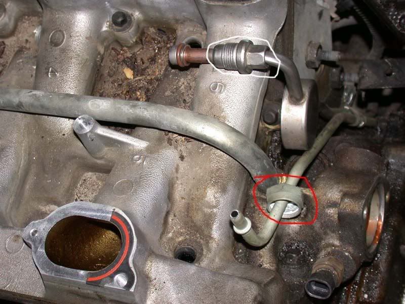 |
the gray one is your HVAC controls
|
make sure you got a wrench on fpr too.. theres a bolt pattern on that to hold on to while you also turn the nut on the fuel line. the bolt on the line needs to be turned TOWARDS the airbox.. Couple of tips. If you disconnect the line clamp down by the rear head the fuel line will come out further. Or the other easy way is to leave the torx connecting the fpr to the fuel rail tight so you have something holding it while you break the nut. And finally if you loosin the bolt on the TB it gives you a little more clearance
P.s> seen you have tb off, fyi you didnt need to pull that off to get to the limg, you can just take it off with the upper plenum |
Quote:
|
what I'm confused if you have the fuel line nut off, then grab a torx and remove the torx scre from the fpr to the fuel rail thenb with a little bit off muscle wiggle the fpr out of the fuel rail.. then with any extra muscle you have wiggle the fpr out of the fuel line. The line is hard to pull out do to the oring doing its job, same goes for the fpr going into the fuel rail
|
Just to clarify: I have the nut circled in white (fuel feed line) in the picture removed/unscrewed, but the red one (FPR) is still in. Okay, I'll go back out and try what you suggested.
|
Steps
(1)pull fpr nut (red one cirlced) (2)pull torx holding fpr to fuel rail (3)wiggle fpr out of fuel rail (4)wiggle fpr out of return line |
Quote:
Okay, and you're sure the FPR nut loosens CW, not CCW? Someone on the GAOC forum says it loosens normally. My issue is still that the FPR nut seems locked up.  |
ccw, if you have two wrenches on all you have to do is turn each one in an opposite direction top one to the left, lower to the right and it will pop off
p.s. Done with work now will be atleat an hour before I'm back on. I can p.m. you my number if you want to call for help |
picture
|
Ahh got it, thanks a lot, I'll have to borrow another crescent wrench and get back to you.
|
Why not just discconect the fuel lines at the quick disconnect?
Could of had it off in 2 minutes... Putting the fuel injectors back in is fun. Make sure to apply WD40 liberally. |
Quote:
Can you elaborate? Because I had no luck with the 2 wrench method... f*ker still does not want to budge!! This is after hitting it twice with PB blaster. -.- |
thought this might help pulled it off alldata
* Tools Required * J 23600-B Torque Angle Meter 1. Remove the upper intake manifold. Refer to Intake Manifold Replacement (Upper) or Intake Manifold Replacement (Lower). 2. Remove the fuel lines at the fuel rail and the bracket. 3. Remove the fuel rail with injectors. Refer to Fuel Rail Assembly Replacement in Powertrain Management. 4. Remove the power steering mounting bolts. Support the pump aside. Refer to Power Steering Pump Replacement in Steering and Suspensions. 5. Remove the inlet cooling pipe from the coolant outlet housing. 6. Remove the heater by-pass at the coolant pump and the cylinder head. 7 Remove the radiator hose at the heater outlet housing. 8. Remove the water outlet housing. Refer to Water Outlet Housing Replacement in Cooling System. 9. Remove both of the valve rocker covers. Refer to Valve Rocker Arm Cover Replacement (Left) or Valve Rocker Arm Cover Replacement (Right). Important: Retain the washers in the same orientation on the center bolts. 10. Remove the lower intake manifold bolts. 11. Remove the lower intake manifold. 12. Loosen the rocker arms. Important: Keep the pushrods in order. The pushrods must be installed in the original position. 13. Remove the pushrods. 14. Remove the intake gasket. 15. Inspect the flatness of the inlet flanges. 16. Clean the following items: o Gasket material from the mating surfaces o Excess RTV sealant from the front and the rear ridges of the cylinder o The block o Sealing surfaces Use degreaser in order to clean the sealing surfaces. Installation Procedure 1. Place a 2 - 3 mm bead of GM RTV sealer P/N 12345739, or the equivalent on each ridge where the front and the rear of the intake manifold contact the block. 2. Install the intake manifold gasket. 3. Install the pushrods. Notice: Refer to Fastener Notice in Service Precautions. 4. Install the rocker arm bolts. Tighten Tighten the bolts to 19 Nm (14 ft. lbs.) + 30 degrees. 4.1. Install the pushrods in their original location. 4.2. Coat the ends of the pushrods with prelube GM P/N 1052356, or the equivalent. 4.3. Intake pushrods are 144 mm (5.75 inch) . 4.4. Exhaust pushrods are 152.5 mm (6.0 inch) . 4.5. Ensure that the pushrods seat in the lifter. 5. Install the lower intake manifold. Notice: Failure to tighten vertical bolts before the diagonal bolts may cause an oil leak. 6. Install NEW lower intake manifold bolts. Revised Updated Torque Specification, Bulletin #vss20030024 The torque specification is a 2-step process; tighten the vertical lower intake manifold bolts (the four middle ones) to 7 Nm (62 lb in). Tighten the diagonal lower intake manifold bolts (two on each end) to 7 Nm (62 lb in). Tighten the vertical lower intake manifold bolts (the four middle ones) to 13 Nm (115 lb in). Tighten the diagonal lower intake manifold bolts (two on each end) to 25 Nm (18 lb ft). 7. Install the valve rocker covers. Refer to Valve Rocker Arm Cover Replacement (Left) or Valve Rocker Arm Cover Replacement (Right). 8. Install the water outlet housing. Refer to Water Outlet Housing Replacement in Cooling System. 9. Install the radiator hose to the thermostat housing. 10. Install the heater inlet pipe to the thermostat housing. 11. Install the fuel lines to the fuel rail and the bracket. 12. Install the fuel rail with injectors. Refer to Fuel Rail Assembly Replacement in Powertrain Management. 13. Install the upper intake manifold. Refer to Intake Manifold Replacement (Upper) or Intake Manifold Replacement (Lower). |
holy sh!t...that was so detailed i even i could prolly do it know.
Congrats bkathsalero, you havea tha powa to give other people discriptive info. I applaud you, no sarcasm. |
Quote:
You need a $8 tool. Its a gas line quick disconnect tool. Follow those two metal lines, theres a disconnect there. The tool slips over the lines and presses the metal tabs up. http://www.autozone.com/autozone/cat...questid=532875 The time this thread has taken... Goto your local parts store and get one of these! lol. If you F'up that fuel rail you WILL BE crying... Plus the O Rings may be bad now... The one thats been disconnected SHOULD be replaced... |
| All times are GMT -4. The time now is 06:21 AM. |
Powered by vBulletin Version 3.6.0
Copyright ©2000 - 2025, Jelsoft Enterprises Ltd.